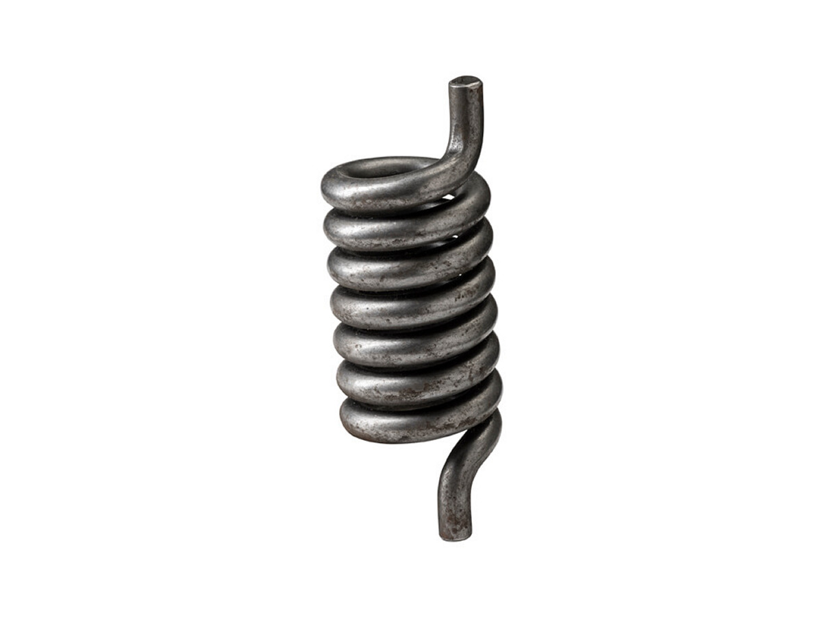
Torsion Springs
A torsion spring is a helical spring loaded by rotating its legs about the coil axis; it stores energy as torque rather than axial force. Its rate is usually expressed in N·mm per degree and can be estimated with k′ = E·d⁴ / (10.8·D·N). Wind direction, leg form, the supporting arbor and the reduction of inside diameter under load all need to be defined.
Product Overview and Project Fit
Custom torsion and double torsion springs for hinges, latches, clamps and automotive mechanisms. Legs, torque and wind direction reviewed per drawing.
Custom torsion springs for hinges, clamps, latches, and automotive locking mechanisms that rely on repeatable torque output.
- Precise Angle
- Stable Torque
- Complex Form
Applications
- Automotive
- Machinery
Processes
- Cold Coiling Process
- Testing
Torsion spring engineering guide
How a torsion spring works
A torsion spring stores energy when its legs are rotated about the coil axis. Despite the name, the wire is stressed mainly in bending, not torsion: each coil bends a little as the legs turn, and the spring pushes back with a torque that rises in proportion to the angle.
The body should be supported on an arbor (a rod through the coils), and the legs should bear on surfaces that keep the load perpendicular to the leg. A spring that is free to tilt or rub on its arbor loses torque and wears.
Torque and rate formulas
Rate per turn: k′ = E·d⁴ / (10.8·D·N), in N·mm per turn. Divide by 360 for N·mm per degree. Torque at the working angle θ: M = k′·θ/360. The constant 10.8 (rather than the theoretical 10.2) allows for friction between coils and on the arbor.
Bending stress at the inside of the coil: σ = K_i·32·M / (π·d³), with K_i = (4C² − C − 1) / (4C·(C − 1)) and spring index C = D/d. Long straight legs add active material; a common estimate is N = N_body + (L₁ + L₂) / (3π·D).
Example: music wire, d = 2 mm, outside diameter 20 mm (D = 18 mm), 6 body turns, E = 206 GPa: k′ ≈ 2,826 N·mm/turn, or 7.85 N·mm/°. At 90° the torque is about 706 N·mm and the corrected bending stress about 980 MPa.
Diameter reduction and arbor clearance
As a torsion spring winds up, its coil diameter shrinks and its body gets longer. The mean diameter under load is D′ = D·N / (N + θ/360). In the example above the inside diameter falls from 16 mm to about 15.3 mm at 90°.
Size the arbor from the smallest inside diameter at full deflection — a common rule is about 90% of that diameter — so the coils do not bind on the rod. Allow for the body growing by roughly one wire diameter for each extra turn wound in.
Wind direction and leg styles
Torsion spring drawings must define:
- Wind direction — left-hand or right-hand, seen from the end of the spring. Mirror-image mechanisms need opposite hands.
- Free angle between the legs and the working angle(s) where torque is specified.
- Leg form — straight tangential legs, radial legs, short hooks, hinged or bent ends — with lengths and bend radii.
- Body form — close-wound (coils touching) or open-wound with pitch to reduce friction.
- Double torsion springs: two opposite-hand bodies joined by a centre loop, acting in parallel.
Torsion spring materials
Material is chosen for stress, environment and temperature:
- Music wire (ASTM A228) and hard-drawn carbon wire (A227) — the usual choice for small and medium springs at room temperature.
- Oil-tempered (A229), chrome-vanadium (A231) and chrome-silicon (A401) — higher stress, shock loading and moderate temperature.
- Stainless steel 302/304 (A313) and 17-7 PH — corrosion resistance; 302/304 has about 6% lower modulus than carbon steel, so the rate falls for the same geometry.
- 65Mn and 60Si2Mn to Chinese GB standards — common equivalents for industrial springs.
What to specify for a custom torsion spring
Send these with the drawing or sample:
- Torque required at one or two defined angles, with tolerance.
- Free angle, wind direction and leg dimensions.
- Arbor diameter and the space available around the body.
- Wire material, finish and operating temperature.
- Expected cycle life and annual quantity.
Drawing inputs to confirm
Use these family-specific inputs to prepare a drawing review covering geometry, service conditions and acceptance. Final parameters are agreed for your project.
- Winding direction, leg lengths/angles and mounting reference
- Torque at specified angles and the permitted motion envelope
- Shaft clearance, leg contact geometry, cycle duty and inspection method
FAQ
How is torsion spring torque calculated?
Torque equals the angular rate multiplied by the deflection angle. The rate per turn can be estimated as k′ = E·d⁴ / (10.8·D·N), where E is Young's modulus, d the wire diameter, D the mean diameter and N the active turns; divide by 360 for the rate per degree.
Which direction should a torsion spring be loaded?
Load a torsion spring in the direction that winds the coils tighter. That direction works with the residual stress left by coiling, so the spring can carry more torque before it takes a set. Loading it to unwind the coils lowers the usable stress, and the spring then needs a larger design margin.
What is a double torsion spring?
A double torsion spring has two coil bodies wound in opposite directions and joined by a U-shaped loop in the middle. The two halves work in parallel, so the torque at the loop is the sum of both bodies. It gives balanced, higher torque across a wider part, such as a lid, door or trap mechanism.
What is the difference between a torsion spring and an extension spring?
A torsion spring is loaded by rotating its legs and returns torque. An extension spring is pulled along its axis and returns a straight-line force. Garage doors use both types: torsion springs on a shaft above the door, or extension springs along the tracks.
Related Articles and Selection Guides
Contact Us
Share your drawing, working load, material and quantity. We will help define the next step toward a manufacturable spring.